Deluge System Design Calculations
Deluge system design calculations. When acti-vated the deluge valve admits water to the piping network and water flows simultaneously from all of the open sprinklers. Without up to date isometric drawings and hydraulic calculations then there is no method of proving to the AHJ or regulatory body that each system is operating as designed when released either when routinely wet testing or a change of status calling for a deluge release. The water supply actually provides 8000 gpm based on main capacity testing.
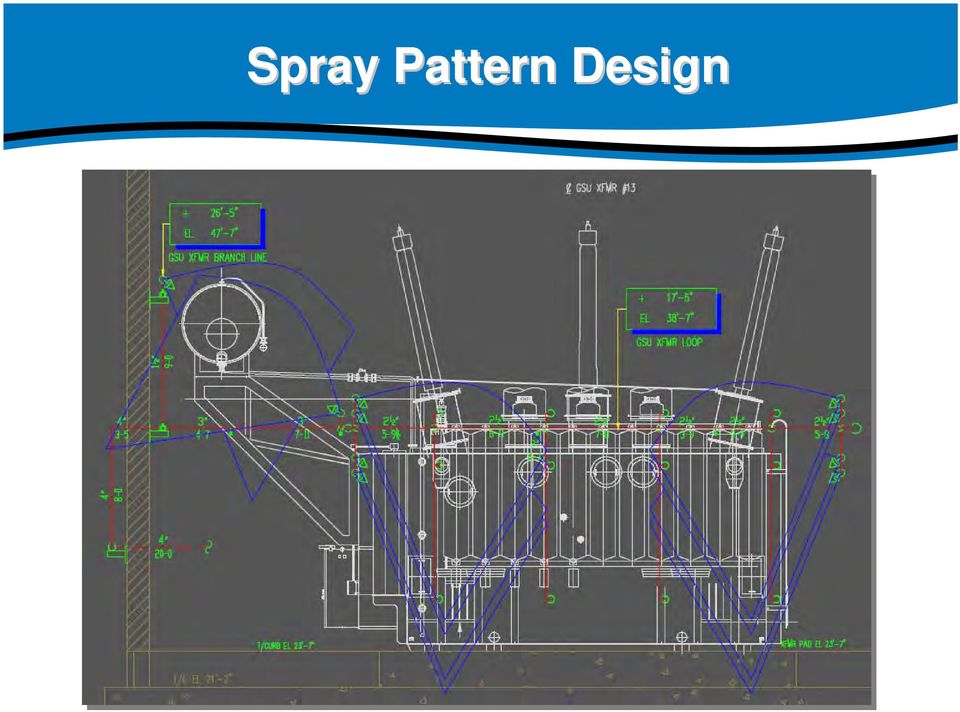
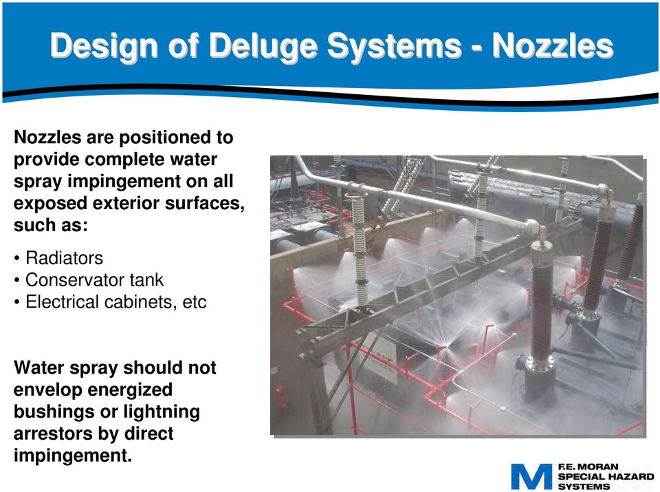
The systems was designed in accordance with FM Global requirements which called for the sprinkler heads to be spaced at 24m apart with a standard fire sprinkler with a K-factor of 80. This system is a water spray deluge system installed on a outside wall to provide a water curtain. Deluge Valve Angle Pattern Conventional Deluge Trim Vertical Conventional Deluge Trim Horizontal Releasing Trims.
Gpm Pipe Diamin Eq. Discharge Criteria 016 Q 108 gpm P 131 psi refused P 300 psi Q 164 gpm Discharge Criteria 024 accepted Therefore Sp. System.
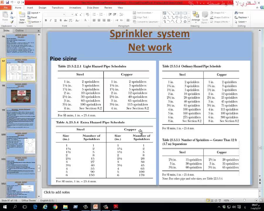
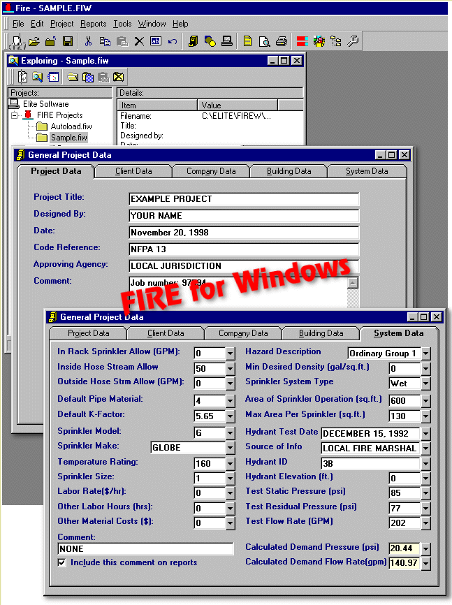
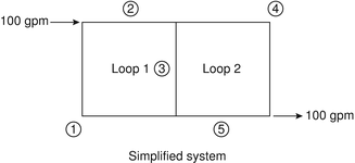
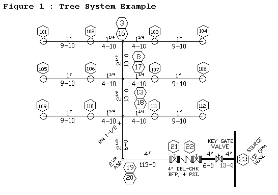
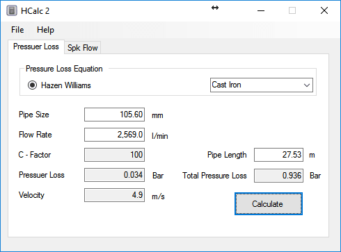
Our example using rough numbers. Pipe length ft C S1 1640 0500 800 120 333 57 N1-N2 3280 1000 3100 120 041 69 N2-N3 6560 1500 2000 120 021 73 N3-N4 9840 2000 900 120 011 74 9840 2000 1500 120. Although firewater systems generally do not suffer from erosion problems because they do not work 24 hours a day it is still important to keep the velocities below a reasonable limit.
Accessories for Deluge. Model G Preaction Systems. This question pertains to hydraulic calculations at the supply and sprinkler sides of a deluge system.
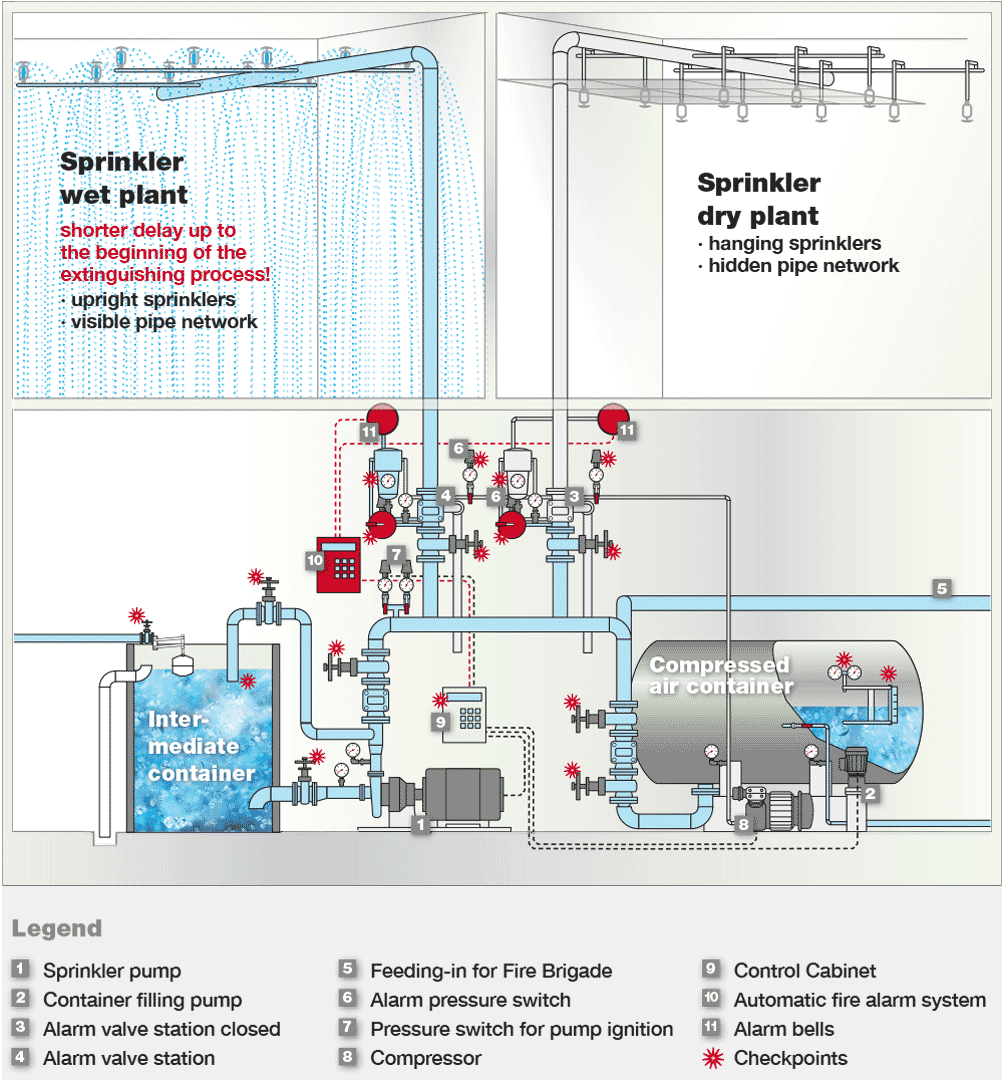
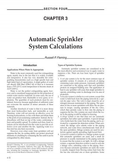
However the minimum head pressure of 14 bar was used this is to insure the sprinkler achieves its full discard pattern in a. Aspecial deluge valve holds back the water from the piping and is ac-tivated by a separate fire detection system. The deluge system requires 4000 gpm based on density requirements through the building.
Now suppose you have a strong water supply. When wet deluge testing SIRON record volumetric flows nozzle pressures deluge.
Flow Control.
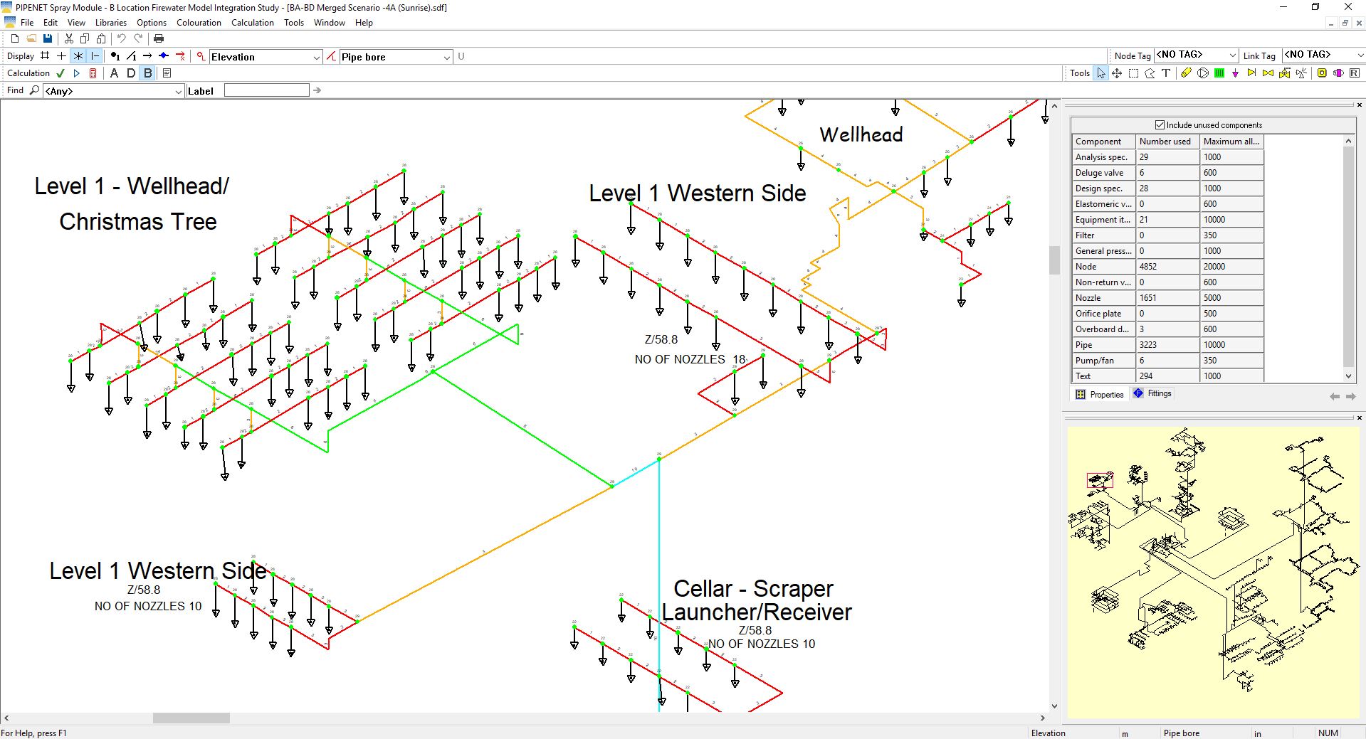
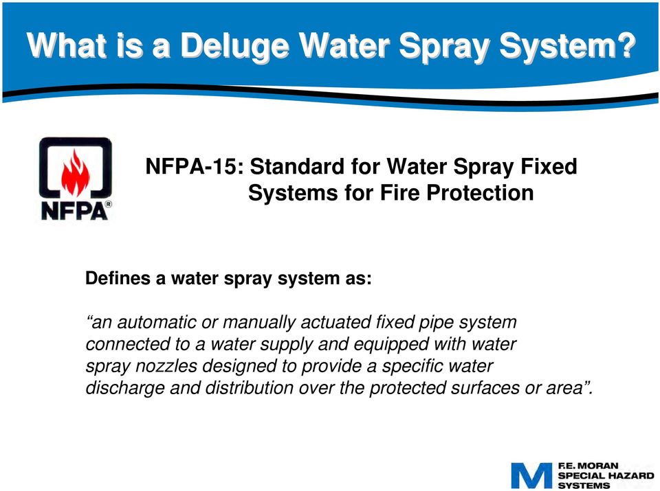
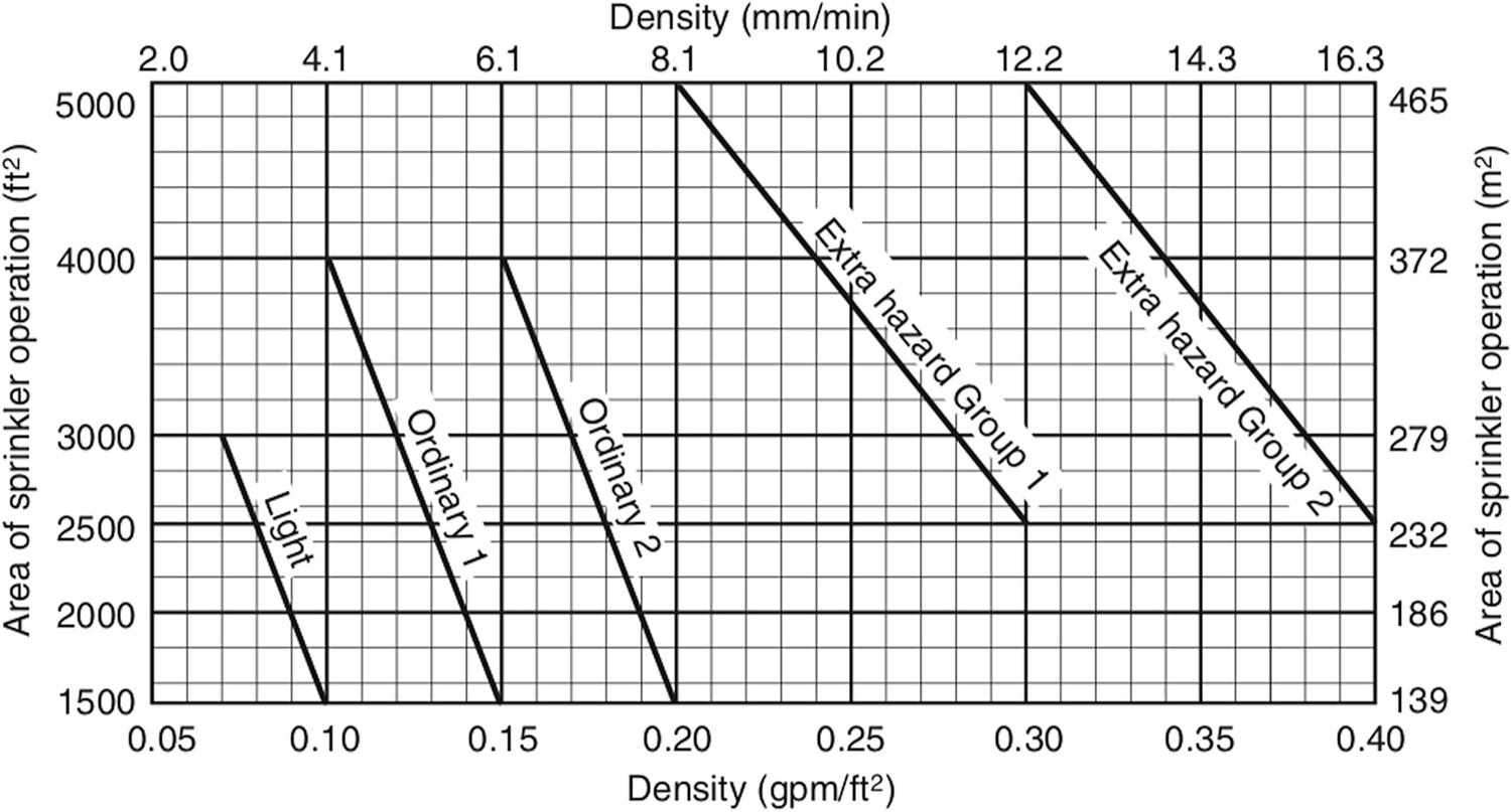
Each deluge system is different and as such they vary in size number of nozzles and fire water demand. This technical manual will cover Viking deluge system design calculation trim parts and their functions as well as describe the proper operation maintenance and repair of. The deluge system requires 4000 gpm based on density requirements through the building. System. The systems was designed in accordance with FM Global requirements which called for the sprinkler heads to be spaced at 24m apart with a standard fire sprinkler with a K-factor of 80. Taking the design density as the governing constraint. Aspecial deluge valve holds back the water from the piping and is ac-tivated by a separate fire detection system. Discharge Criteria 016 Q 108 gpm P 131 psi refused P 300 psi Q 164 gpm Discharge Criteria 024 accepted Therefore Sp. Although firewater systems generally do not suffer from erosion problems because they do not work 24 hours a day it is still important to keep the velocities below a reasonable limit.
Each deluge system is different and as such they vary in size number of nozzles and fire water demand. This technical manual will cover Viking deluge system design calculation trim parts and their functions as well as describe the proper operation maintenance and repair of. However the minimum head pressure of 14 bar was used this is to insure the sprinkler achieves its full discard pattern in a. System. Each deluge system is different and as such they vary in size number of nozzles and fire water demand. Aspecial deluge valve holds back the water from the piping and is ac-tivated by a separate fire detection system. Deluge systems are used for pro-tection against rapidly.

















Post a Comment for "Deluge System Design Calculations"